1. Terminology
On this page, we introduce you to the central concepts of the ray tracer. Before we start, we need to point out that "ray tracer" will have two meanings:
-
Ray tracer can refer to the whole piece of software.
-
Ray tracer can also refer to the specific part that traces rays.
To disambiguate between the two meanings, we’ll write RayTracer when we mean the whole, and ray tracer to designate the part.
2. Concepts
2.1. Pipeline
A pipeline is a series of operations that are to be performed one after the other. Each segment of a pipeline receives an input, processes it, and (generally) produces some output. The different segments are linked together so that one’s segment output is the next segment’s input. The simplest pipeline for our purposes is the one consisting of just one segment:

This pipeline consists of just the renderer segment. A renderer takes a scene, renders it, and outputs the results as a bitmap. Pipeline segments are shown as rectangles, while the objects they receive or produce are represented by circles.
This pipeline is not very useful, as the bitmap exists only in memory and we’d prefer having it written to file. There’s a separate pipeline segment available to you for exactly this purpose:
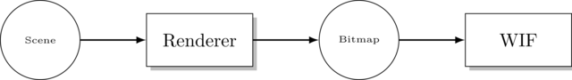
Here, the bitmap produced by the renderer is passed on to the WIF pipeline segment, which writes the bitmap to file. WIF is the name of the graphics file format (like jpeg or png). The reason we use our own image format is to be able to easily output it (WIF is very simple) and supports animations.
There is no arrow leaving the WIF rectangle because it does not produce any output. You can
see it as a void-returning function. It takes the bitmap, writes it to file, and that’s it.
A pipeline segment that accepts input is called a consumer. One that produces output is called a producer. Most pipeline segments are both. WIF is one of the few segments that is only a consumer, not a producer.
All functionality related to pipelines can be found in the pipeline module.
Examples of other pipeline segments are
-
The animation pipeline segment belongs in front of the pipeline: its purpose is to create a series of
Sceneobjects, each representing the state of the scene at some specific time. -
The
renderer()segment takes a scene and converts it into an image. -
The
wif()segment converts images into the WIF file format. -
The
base64()segment takes binary data and encodes it using base64. -
The
stdout()segment prints out all data it receives to STDOUT. -
Motion blur comes after the renderer and adds bitmaps together, thereby creating a motion blur effect.
2.2. Scene
A scene defines the virtual world and the camera we use to take a picture of it. For example, consider the picture below:
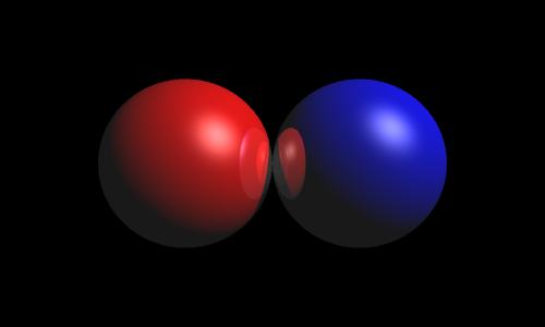
This rather boring scene consists of two reflective spheres, one red and one blue. It also contains a light that shines from the upper right (notice the bright spots on both spheres.) Lastly, the scene also defines where the camera is located, i.e. right in front the two spheres.
2.2.1. Anatomy of a Scene
We define what a scene is more formally. A scene has three components:
- Root
-
The root defines all the shapes in the scene. In the example above, the root is what defines the location, size and color of both spheres.
- Light Sources
-
A list of all light sources. In the example above, there is one white light located to the upper right.
- Camera
-
The location and orientation of the camera. In the example above, the camera is placed in front of the two spheres and looks straight at them.
2.3. Renderer
The renderer’s purpose in life is turning scenes into bitmaps. There are different types of renderers, each of which will produce a different rendition of the scene. The picture above was produced by the standard renderer, which performs no fancy tricks. Other renderers are
-
The Cartoon Renderer gives the scene a cartoony look.
-
The Edge Renderer only draws the edges of objects.
Different types of renderers have different components, so for now we will
pretend only the standard renderer exists.
Go find the declaration for the factory function in the code.
It is located in the renderers module, in the file standard-renderer.h.
As you see, it requires the following inputs:
- Image size
-
The size of the output image. The example above has size 500×300.
- Sampler
-
This is a more advanced feature which will be explained later in greater detail. Suffice it to say that it determines image quality. To create a sampler, you can look what factory functions are available in the
raytracer::samplersnamespace. - Ray tracer
-
Which ray tracer to be used. This is the actual work horse: it is the ray tracer that performs the heavy duty work of determining colors, shadows, reflections, etc. The renderer basically just asks the ray tracer to determine what color light enters from a certain direction, and the renderer will then paint the corresponding pixel in that color. We will discuss ray tracers in detail shortly.
- Task scheduler
-
Like samplers, this is more advanced stuff. A task is a unit of work that needs to be performed. Ray tracing involves many such units of work. The task scheduler will, given a list of tasks, perform them. So, in essence, it’s just an object faking a loop. What makes it interesting is that a more advanced scheduler will be able to assign tasks to different threads, thereby performing the tasks in parallel, resulting in a large performance boost.
Once you’ve created a renderer, you can feed it a scene using the render method
(see renderers/renderer.h), and it will give you a nice bitmap in return.
2.4. The Ray Tracer
As mentioned before, the ray tracer is where the actual works gets done. It is responsible for following light rays around the scene and determining the color of each object, taking into account lights, materials, reflection, refraction, etc. We won’t develop all these features in one go but instead incrementally.
Here’s a list of the ray tracer extensions. Each is built upon the previous one.
Go take a look in raytracers/ray-tracer.h and you’ll find that ray tracers offers only a single method: trace.
This method takes two parameters: a scene and a ray. The ray tracer then traces the ray, i.e. computes
what object in the scene it hits and finds out what color the object has at that point.
If the object is transparent, the ray tracer will (if it supports refraction at least) compute
how the ray passes through the object. If the object is reflective, the ray tracer must
compute in which direction the ray gets reflected, and so on.
2.5. Primitives
As discussed previously, the scene consists of lights, a camera and a root, where the root is that part of the scene that describes the actual objects in 3D space. The root is built out of primitives.
The primitives are the building blocks for scenes. Examples are
You can also combine primitives, yielding new primitives.
-
Unions
-
Intersections
-
Differences
A more abstract kind of primitive is the bounding box accelerator, which is invisible but allows to dramatically speed up ray tracing, enabling the rendering of scenes involving millions of primitives.
2.6. Light Sources
Light sources specify where light comes from. Without them, the (standard) renderer would just produce a boring black bitmap. If that’s all we wanted, we wouldn’t go to the trouble of defining cameras and primitives and all that.
There are multiple kinds of lights.
-
Omnidirectional point lights are the simplest: it’s akin to an infinitely small lamp that emits photons uniformly in all directions.
-
Directional lights represents lights that are infinitely far away. For example, sunlight can be approximated by a directional light.
-
Spotlights are point lights that only shine in a specific direction.
-
Area lights make lights a bit more realistic: they’re not infinitely small anymore. This results in soft shadows (penumbras).
2.7. Cameras
After having defined which objects (primitives) the scene contains and what light sources there are, we need to specify a camera.
The most obvious effect a camera has on the final result is that
its location determines from what point of view the scene
is rendered. For example, we can put the camera high in the sky or low to the ground.
In the RayTracer, the location of the camera is represented by a Point3D and
generally referred to as the eye’s position.
We of course also need to specify the camera’s orientation: what is it looking at?
In the RayTracer, this corresponds to the look_at, of type Point3D.
Even with the position and the look_at point, the orientation of the camera is not yet fully determined:
it is possible to tilt the camera. For example, you can choose to turn the camera upside down.
How the camera is positioned is determined by the up-vector (of type Vector3D). If you
want the camera to stand up right, choose \((0, 1, 0)\) as up-vector. To turn the camera upside down,
take \((0, -1, 0)\), etc.
Given this information, the camera will generate rays originating in the eye and going through each pixel of the canvas/bitmap. The renderer will ask the ray tracer to follow each of these rays around the scene, in order to determine what color photons arrive from that direction.
However, there is no single way of generating these rays, each way corresponding to a different type of camera.
-
The perspective camera is the one you are most familiar with: your eye works the same way.
-
Orthographic cameras is a camera without perspective.
-
Fisheye cameras add a spherical quality to rendering.
-
Depth of field is a perspective camera but with depth of field added to it, so that out-of-focus shapes are blurred.
3. Ray Tracing from A to Z
Now that we’ve seen all important concepts, we explain how they are used in practice for ray tracing.
At the center of the action lies the renderer. The renderer has at its disposal
-
The scene, consisting of a camera, a root and lights.
-
A ray tracer.
-
A task scheduler.
-
A sampler.
-
The expected bitmap’s size.
The renderer’s job is to produce a bitmap. So, it creates a bitmap of the requested size (say, for the sake of simplicity, 16×10), which is initialized with black pixels. Now comes the interesting part: assigning the correct color to each pixel.
The renderer needs to process each pixel in turn, so it loops for \(x\) going from 0 to 16 at \(y\) going from 0 to 10. Through each pixel with coordinates \((x, y)\), a ray has to be cast and followed around the scene. The question is: for a given pixel, which rays need to be cast? This question can only be answered by the camera.
Unfortunately, the camera speaks a slightly different language. Whereas pixel coordinates range (in our case) \([0,16\) \times [0,10]] in steps of 1, the camera works only with coordinates in \([0, 1\) \times [0, 1]].
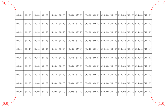
Notice the differences between the pixel and camera coordinates: * A pixel’s y-coordinates (black) grows higher from top to bottom. Camera y-coordinates (red) go in the opposite direction: 0 at the bottom, 1 at the top. * Pixel coordinates are discreet, i.e. whole numbers. Camera coordinates are continuous, i.e., real numbers.
In order to translate pixel coordinates \([0,16\) \times [0,10]] to camera coordinates \([0,1\) \times [0,1]] we rely on a rasterizer. We can give this rasterizer the rectangle \([0, 1\) \times [0,1]] and ask it to divide it into \(16 \times 10\) subrectangles. Asking for the subrectangle with coordinates \((0,9)\) then yields the bottom left rectangle \([0,0\) \times [\frac{1}{16}, \frac{1}{10}]]. This is called the pixel rectangle and corresponds to the area the pixel covers in the bitmap.
We now have this pixel rectangle for which we need to determine a single color, which we will use to paint the entire pixel. But this rectangle consists of many points, and each of these points can have a different color. Which point’s color do we need to pick to fill the entire pixel with?
The gray area represents the pixel area. Should we determine the color of the middle of the pixel rectangle, i.e. \(P\)? Or perhaps the upper left corner \(Q\)? Or will \(R\) work too? Or maybe we should compute the color all three points and average out the results?
All these possibilities lead to slightly different results. The responsibility of deciding of how many points and which points these are falls on the sampler's shoulders: a sampler will, given a rectangle, return a list of points. Examples for samplers are
-
Standard sampler: always picks the middle of the pixel rectangle.
-
Random sampler: takes \(N\) random points in the pixel square, where \(N\) can be chosen freely.
-
Stratified sampler: subdivides the pixel rectangle into subpixels and chooses the center of each.
-
Jittering stratified sampler: subdivides the pixel rectangle into \(N \times M\) subpixels and chooses a random point in each.
-
Half-jittering stratified sampler: subdivides the pixel rectangle into \(N \times M\) subpixels and chooses a random point in each, but stays aways from the borders.
-
n-Rooks sampler: subdivides the pixel rectangle into \(N \times N\) subpixels and chooses a random point in \(N\) of them.
-
Multijittered sampler: combination of other samplers.
Now we have our pixel rectangle and the different points inside this pixel rectangle we wish to determine the color for. We then ask the camera which rays correspond to each of these points and give these rays to the ray tracer.
The basic ray tracer is very simple. It receives a ray and has access to the scene data. It asks the scene’s
root where the ray hits an object using find_first_positive_hit. Not any intersection will do:
the ray tracer needs to have the intersection that’s closest to the eye and is in front of the eye.
This is similar to the situation where if you take a picture of a forest, the picture will only
show the trees that are not obscured by other trees (= first hit), and trees behind the camera will not
show on the picture either (= only positive hits).
Once the ray tracer has gotten hold of the first positive hit, it will look for the Material in the Hit data structure.
This determines the color of the hit. This suffices for a simple ray tracer. More advanced ray tracers will perform extra computations:
-
Lighting: a ray tracer can compute which light sources are around and how many photons reach the hit location.
-
Shadowing: a ray tracer can check whether these photons are blocked by other objects in the scene.
-
Reflection: it can compute the reflection of the ray and trace this second ray to find out what color gets reflected.
-
Refraction: a ray can be bent (i.e. not travel in a straight line) when it reaches an object boundary.
In summary,
create bitmap of size width x height
create rectangle [0,1] x [0,1]
create rasterizer that subdivides rectangle into width x height pixel rectangles

for each x in range(0, width)
  for each y in range(1, height)
    determine pixel rectangle of pixel at (x, y)
    colors = empty list

    sampler picks random points in rectangle
    for each point
      camera generates rays for each point

      for each ray
        ray trace ray, resulting in color c
        store c in colors list

    compute average of all colors
    write average to bitmap to (x, y)